Planning, Configuring And Ordering A Vesta System
The products page groups Vesta products into logical categories and provides links to detail pages with prices, part numbers, and specifications. Vesta hardware cannot currently be ordered online. We suggest that you contact us and place a deposit, then develop an exact list of components and options with support from our application engineering team. We can also provide a quote and invoice if desired. Contact us via email at [email protected] or by telephone or text at 614-918-VECS (614-918-8327).
System Overview
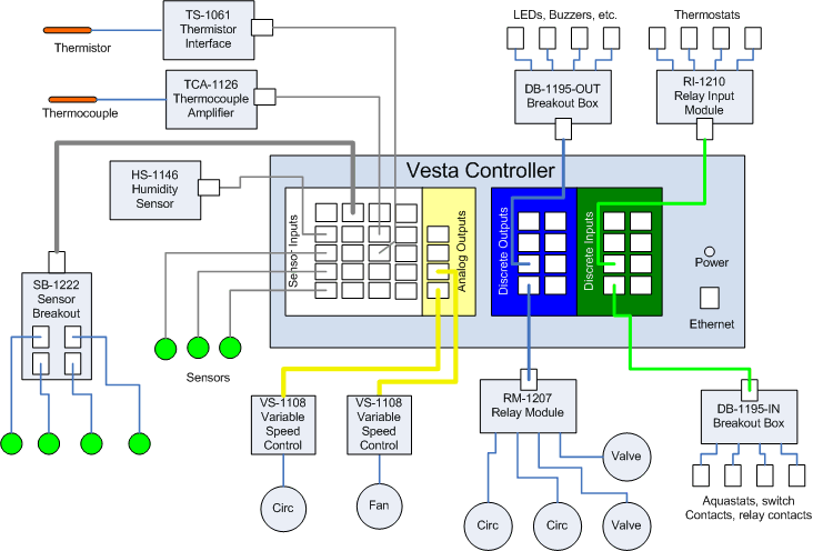
A typical Vesta installation includes a Vesta System Controller and a variety of sensors, relay boxes, and other accessories. The diagram below shows how some of the more common devices connect to the Vesta controller.

The products page contains a list of all standard Vesta system components with a link to more detailed information on each. Products can be ordered directly from the products page or from the item detail pages.
Cables
All sensors and variable speed controls connect via standard 4 conductor (RJ11) cables. Each sensor comes with a 25' cable - special lengths are available on request. Relay modules and breakout boxes connect via standard Cat5 (Ethernet style) cables which are not included.
Planning
Specifying and installing a Vesta system requires some planning. We suggest the process described below. Links to tools and documentation are provided where relevant.
Spreadsheet
When you place a deposit on a controller, we create an on-line spreadsheet that can be used to help plan and document your configuration. The spreadsheet has tabs along the bottom for basic configuration, sensors, discrete inputs, and discrete outputs. We'll create a copy that is specific to your serial number and can serve as long-term documentation of your system configuration. While it's not required, using the spreadsheet makes it easier for us to review and discuss the details of your installation. Screenshots of portions of this spreadsheet are shown below.
Physical Location
Decide where the controller will be mounted. It needs to be a relatively clean and dry location with access to power and Ethernet. To reduce cable lengths, it should be close to most of the equipment that is to be monitored and controlled. It can sit on a shelf or be mounted to a wall. It should be accessible for service, and there should be access to see the connector legends on the sides of the controller. If you want to use the LEDs on the front panel to indicate system status, then it needs to be mounted so they're visible.
Network Configuration
The Vesta controller is a network device, so it needs to be configured for your network. Directions for getting the necessary network information are here. This information can be provided directly to us or entered in the on-line spreadsheet.
Sensors
We are continually adding sensors and accessories. Contact us if you don't see what you need.
The Vesta controller can accommodate up to 16 sensors (8 for the Vantage model). For each sensor that you need, you'll have to determine a few things:
- Sensor type (TS-1058 temperature sensor is the default)
- Installation location and method
- Required cable length
- Brief descriptive name
Using our spreadsheet (or a piece of paper) list the sensors you'll need and the type, location, cable length, and name for each.
In the example below, the 'Outdoor Temp' sensor will need a custom cable length. The 'Oil Flue Temp' is a thermocouple. Channels 5 through 8 are on the roof and are connected to a breakout box in the attic. The breakout box will need a 40' cable.

Cable Length
Be very careful measuring cable lengths. It's easy to underestimate. The best approach is to physically run a wire exactly where the sensor cable will be routed and then measure its length. Standard sensors come with a 25' cable. If this is too short, there are three options:
- Order a custom cable. These are available for a nominal added cost.
- Order a cable extension and mating connector.
- Use a sensor breakout box (not currently listed on our product page - available by request)
The third option is useful if there are several sensors at a distant location such as the rooftop. The sensor breakout box handles a group of four sensors and can be connected with a standard Cat5 Ethernet type cable. This allows you to run a single cable to the remote location and then connect up to four sensors to the breakout box. If you use a sensor breakout box, note that information on the planning sheet for the group of sensors that will be connected to it. Sensor cable lengths in this case are from the breakout box to the installation location for each sensor.
If the cable is too long, you can either coil the excess or cut to length and install a new connector. Sensor cables use standard RJ11 crimp connectors, available on request. We can also make each cable to length - there's a nominal additional charge for making custom length cables.
